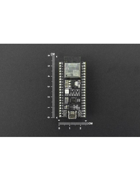
ESP32-S2-MINI-1 is a generic Wi-Fi MCU module that integrates ESP32-S2FH4 chip. ESP32-S2-MINI-1 comes with a PCB antenna and features a 4 MB SPI flash.
.
Description of Components
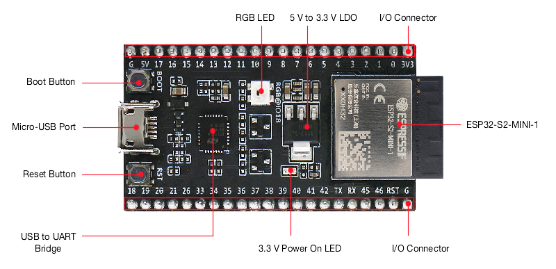
.
|
Key Component<span "="" style="box-sizing: border-box; font-size: 10.5pt;"> |
<span "="" style="box-sizing: border-box; font-size: 10.5pt;">Description |
|
ESP32-S2-MINI-1<span "="" style="box-sizing: border-box; font-size: 10.5pt;"> |
ESP32-S2-MINI-1 is a generic Wi-Fi MCU module that integrates ESP32-S2FH4 chip. ESP32-S2-MINI-1 comes with a PCB antenna. And the module features a 4 MB SPI flash.<span "="" style="box-sizing: border-box; font-size: 10.5pt;"> |
|
3.3 V Power On LED<span "="" style="box-sizing: border-box; font-size: 10.5pt;"> |
Turns on when the USB power is connected to the board.<span "="" style="box-sizing: border-box; font-size: 10.5pt;"> |
|
USB to UART Bridge<span "="" style="box-sizing: border-box; font-size: 10.5pt;"> |
Single USB-UART bridge chip provides transfer rates up to 3 Mbps.<span "="" style="box-sizing: border-box; font-size: 10.5pt;"> |
|
I/O Connector<span "="" style="box-sizing: border-box; font-size: 10.5pt;"> |
All available GPIO pins (except for the SPI bus for flash) are broken out to the pin headers on the board. Users can program ESP32-S2FH4 chip to enable multiple functions such as SPI, I2S, UART, 12C, touch sensors, PWM etc. For details, please check the table below.<span "="" style="box-sizing: border-box; font-size: 10.5pt;"> |
|
Reset Button<span "="" style="box-sizing: border-box; font-size: 10.5pt;"> |
Reset Button.<span "="" style="box-sizing: border-box; font-size: 10.5pt;"> |
|
Micro-USB Port<span "="" style="box-sizing: border-box; font-size: 10.5pt;"> |
USB interface. Power supply for the board as well as the communication interface between a computer and the ESP32-S2FH4 chip.<span "="" style="box-sizing: border-box; font-size: 10.5pt;"> |
|
Boot Button<span "="" style="box-sizing: border-box; font-size: 10.5pt;"> |
Download button. Holding down Boot and then pressing Reset initiates firmware Download mode for downloading firmware through the serial port.<span "="" style="box-sizing: border-box; font-size: 10.5pt;"> |
|
RGB LED<span "="" style="box-sizing: border-box; font-size: 10.5pt;"> |
Addressable RGB LED (WS2812), driven by GPIO18.<span "="" style="box-sizing: border-box; font-size: 10.5pt;"> |
|
5V to 3.3V LDO<span "="" style="box-sizing: border-box; font-size: 10.5pt;"> |
Power regulator that converts a 5 V supply into a 3.3 V output. |
.
Pin Header
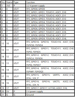
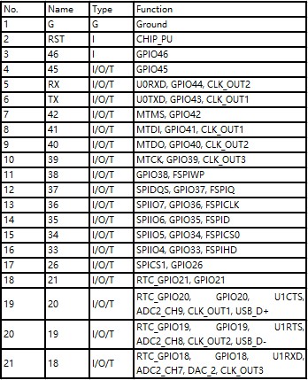
The tables below provide the Name and Function of I/O header pins on both sides of the board, the numbering and names are the same as in the schematics in the picture above.
.
J1
 .
.
.
J2
.
SPECIFICATION
- ESP32-S2FH4 chip, Xtensa single-core 32-bit LX7 microprocessor
- 128 KB ROM
- 320 KB SRAM
- 16 KB RTC SRAM
- 40 MHz crystal oscillator
- 4 MB SPI flash
- Operating Voltage/Power supply: 3.0~3.6 V
- Operating Temperature Range: –40~85°C
.
SHIPPING LIST
- ESP32-S2-DevKitM-1 Demo Board ×1

